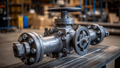
Choosing a 2 inch gate valve is about more than matching a pipe diameter. The valve must suit the fluid, pressure, temperature, and operating conditions. A stainless-steel model may suit a corrosive process, while a compatible bronze or iron body may work in other systems. Check the manufacturer’s pressure and temperature ratings against your actual service conditions. A two-inch connection alone does not confirm compatibility.
Valve specialist Alex Morgan is an illustrative, fictional expert voice, not a verified industry source. The original line for this guide is: “Choose for the service conditions first; size alone is never the whole answer.” Use that as a reminder, not as a sourced quotation. Confirm the connection type, body material, trim, and end-to-end dimensions on the product data sheet. Also consider whether the valve will be opened and closed occasionally or used in a way that could cause wear. It matters.
A gate valve is generally intended for fully open or fully closed service, not precise flow regulation. Look for clear markings and a traceable manufacturer, then compare the details with your piping plans. A small mismatch can mean rework. Even experienced buyers can overlook installation clearance around the handwheel. Measure the space before ordering. This guide will help you compare the practical details, ask better supplier questions, and make a more informed choice. One limitation remains: product data cannot replace a qualified review of unusual or safety-critical service conditions.
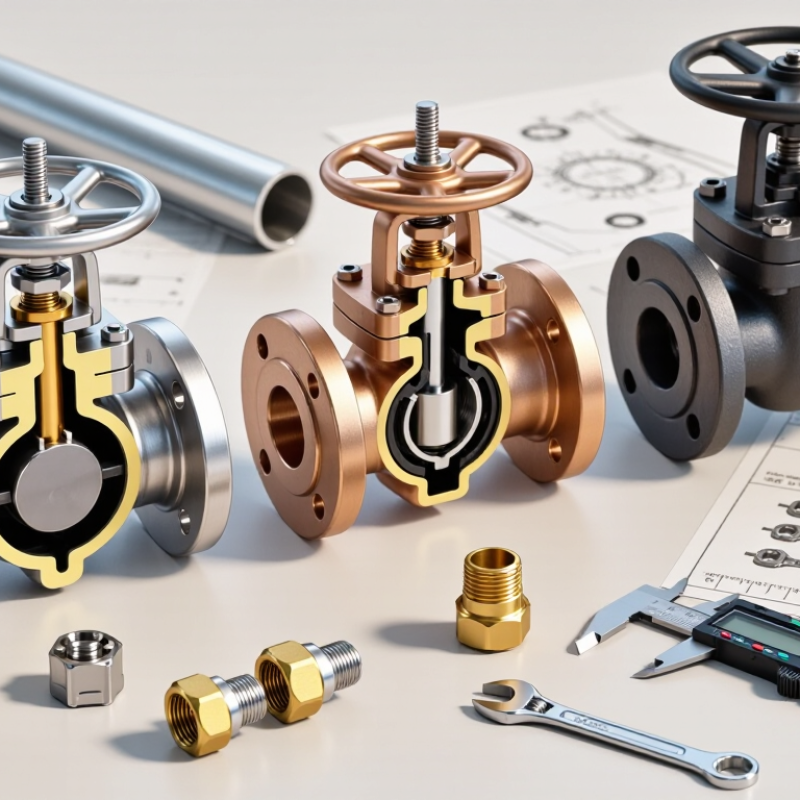
How to Choose a 2 Inch Gate Valve?
Define the Fluid, Operating Conditions, and System Requirements
A 2-inch label describes a nominal pipe size, not necessarily the valve’s exact opening. Start by identifying the fluid, including any solids, grit, or chemical properties that could affect valve materials. Water, steam, and viscous fluids place different demands on the body, trim, and seals. Check the fluid temperature and pressure during normal operation, startup, and shutdown. A single operating figure can miss important peaks.
Tips: Confirm the pipe standard, pressure rating, and end connection before ordering. Check the available installation space, too.
Then define what the valve must do. Gate valves are generally intended for fully open or fully closed service, not frequent throttling. Confirm the required shutoff performance, flow direction, operating frequency, and whether manual or powered operation is needed. Think about access for handwheel movement and future maintenance. That detail is easy to overlook. I would verify the actual system conditions with current drawings and operating data rather than rely on assumptions; records can be incomplete, and a quick check may reveal that. Choose a valve whose materials and rating suit the whole system, not just the pipe diameter.
A “2-inch” gate valve usually refers to its nominal pipe size, not a body or bore measuring exactly two inches. Check the pipe marking and the valve’s technical drawing before ordering. A tape measure can help, but outside diameter alone may not identify nominal size, especially when pipe materials or standards differ. Do not guess. A quick visual comparison can be misleading.
Next, match the valve ends to the existing piping. Common options include threaded, flanged, grooved, and welded connections. For threaded ends, confirm the thread standard and gender; similar-looking threads may not seal correctly. For flanged ends, check the flange rating, facing, bolt pattern, and gasket requirements. Grooved connections need compatible groove dimensions and a suitable coupling. Small mismatches matter. A valve may be listed as 2-inch and still fail to fit the line. Before purchase, compare the connection details with the pipe specification and installation space. If the records are incomplete, measure the fittings and ask a qualified supplier to verify the dimensions. I would not rely on the size label alone; it is an easy detail to overlook.
For a 2-inch gate valve, match the body and trim materials to the fluid, not just the pipe size. Carbon steel may suit many water or oil services, while stainless steel can resist certain corrosive fluids. However, stainless steel is not automatically the right choice for every chemical. Check compatibility with the exact fluid, concentration, and operating conditions. Small details matter. Also consider the stem, disc, and seat: a compatible body cannot compensate for unsuitable internal parts.
Tips: Confirm the valve’s pressure-temperature chart for its exact material and design. Do not guess. A pressure class alone does not mean the valve can handle the same pressure at every temperature.
Temperature can change the allowable working pressure, especially in hot service such as steam. Compare the expected operating pressure and temperature with the valve’s published rating, and allow for startup peaks or brief temperature swings. Check the end connection and applicable design standard, too; they affect how the valve fits and performs in the line. This selection is not always tidy. If service data is incomplete, pause and verify it with the project engineer or a qualified valve supplier before specifying the valve.
For a 2-inch gate valve, start with its job: dependable isolation, not frequent throttling. A solid wedge is simple and common; a flexible wedge can better accommodate some temperature-related movement. Check the body material, pressure class, and seat materials against the actual fluid and operating conditions. Small details matter.
Stem design affects both visibility and space. A rising stem shows valve position clearly, but needs overhead clearance as it opens. A non-rising stem keeps the installation compact, though position may be less obvious and stem threads can contact the process. Neither design is automatically better. Debris and maintenance access can change the choice.
Actuation ranges from a handwheel to geared, pneumatic, or electric operators. Manual operation is often practical at this size, unless access, operating frequency, or required torque makes it difficult. The U.S. Department of Energy’s 2002 United States Industrial Electric Motor Systems Market Opportunities Assessment estimated motor-driven systems used 63% of U.S. manufacturing electricity. That figure describes whole industrial systems, not individual valve actuators; still, it supports considering power and maintenance across a site. Tips: Confirm the valve’s torque requirement at maximum differential pressure, and check actuator clearance against nearby pipework. A neat drawing can miss a real obstruction.
A 2-inch gate valve should match the standards required for its service, not just the pipe size. “Two inch” usually refers to nominal size; check the specified connection dimensions and pressure class. Confirm the applicable piping, material, and testing standards for the system. Requirements can differ with fluid, temperature, pressure, and installation location. Check the project documents and local rules, then verify the valve’s markings and technical data. Do not assume a familiar end connection will fit. That mismatch is costly.
Maintenance needs matter just as much. Leave enough clearance to turn the handwheel and remove the bonnet or packing, if service requires it. A valve buried behind equipment may be compliant on paper but difficult to inspect. Plan isolation and drainage before installation, especially where trapped liquid could remain in the body. Gate valves are generally intended for fully open or fully closed service, not routine throttling. Debris can score the seating surfaces. Cycle the valve at an interval suited to the system, and inspect for leaks, stiff operation, or stem corrosion. Keep records of checks and repairs. The interval may need adjustment; actual operating conditions are not always predictable.
| Selection Dimension | What to Check for a 2 Inch Gate Valve | Applicable Standard or Guidance | Why It Matters |
|---|---|---|---|
| Nominal size and pipe connection | Specify NPS 2 (DN 50), then confirm the end type: flanged, threaded, socket-weld, or butt-weld. Check that the connection matches the piping specification. | ASME B16.5 covers pipe flanges and flanged fittings in its stated size and pressure-class scope. ASME B1.20.1 covers NPT pipe threads. | NPS 2 is a nominal size, not a promise that the valve bore or pipe inside diameter measures exactly 2 inches. Connection dimensions and tolerances must match the mating piping. |
| Valve design and construction | Choose a design appropriate to the service, such as a bolted-bonnet steel valve, compact forged-steel valve, or bronze valve. Confirm materials, trim, bonnet arrangement, and applicable end connections. | API 600 covers bolted-bonnet steel gate valves; API 602 covers compact steel gate valves in its specified size range, including NPS 2; MSS SP-80 covers bronze gate valves. | These standards address different valve designs and materials. Do not assume that one standard applies to every 2 inch gate valve. |
| Pressure and temperature rating | Check the required operating and design pressure and temperature against the valve’s material and pressure class. Verify any limits for the selected body, bonnet, seat, and stem materials. | ASME B16.34 provides requirements including pressure-temperature ratings for covered valves. Applicable product standards and the project piping code may add requirements. | A pressure class alone does not establish a universal working pressure at every temperature. Ratings depend on material and temperature, so confirm the manufacturer’s certified rating for the exact configuration. |
| Face-to-face and installation space | For a flanged valve, confirm the required face-to-face dimension, handwheel clearance, stem travel, and access for operation and maintenance. | ASME B16.10 specifies face-to-face and end-to-end dimensions for covered valve types and sizes. | Matching the standard dimension helps with interchangeability and avoids piping rework. Check the specific valve type and class because dimensions may vary. |
| Inspection and pressure testing | Request documentation for the required inspection and pressure tests, including the test procedure, acceptance criteria, and test medium where specified by the purchase requirements. | API 598 covers inspection and testing of valves within its scope. The contract, product standard, and applicable code determine which requirements apply. | Testing requirements should be agreed before purchase; they can differ by valve type, service, and project specification. |
| Fluid compatibility | Verify body, wedge, seat, stem, packing, and gasket materials against the fluid, concentration, temperature, contaminants, and expected corrosion or erosion conditions. | Use the applicable material requirements in the selected valve standard and the project’s materials and corrosion-control specifications. | Material compatibility cannot be determined from nominal size alone. A mismatch can lead to leakage, corrosion, or shortened service life. |
| Operating conditions | Confirm whether the valve is intended for isolation, how often it will operate, the required closing direction, and whether manual operation is suitable. | Follow the valve manufacturer’s operating instructions and the project’s operating and safety requirements. | Gate valves are generally used for on/off isolation and are not intended for routine throttling unless the design and service are specifically approved for it. |
| Routine inspection | At a service-based interval, inspect for external leakage at the packing and body joints, corrosion, damage, obstructed access, and signs of abnormal operation. | Set inspection intervals using the asset maintenance program, service severity, risk assessment, and manufacturer guidance. | There is no single inspection interval suitable for every installation. Adjust frequency to the fluid, operating conditions, and consequences of failure. |
| Operation and lubrication | Operate the valve using its handwheel or approved actuator. Lubricate only designated points with compatible lubricant and only as directed by the manufacturer. | Follow the manufacturer’s maintenance instructions and site isolation and safety procedures. | Forcing a stuck valve or applying unsuitable lubricant can damage the stem, packing, or internal parts. Never use the valve as a lever or apply unapproved extensions. |
| Packing and leakage maintenance | If stem leakage occurs, follow the manufacturer’s procedure for packing adjustment or replacement. Depressurize and isolate the line before maintenance unless an approved procedure specifically permits otherwise. | Use the valve’s maintenance instructions and site lockout, depressurization, and hazardous-fluid controls. | Packing work on a pressurized valve can create serious hazards. Replace packing with a compatible specified material and verify operation after maintenance. |
| Records and final verification | Record the valve tag, NPS, end connection, materials, pressure class, applied standards and editions, test documents, inspection findings, and maintenance performed. | Follow project documentation requirements and the site’s asset-management system. | Complete records help confirm that the installed valve matches the piping specification and support safe, consistent future maintenance. |
Note: Confirm the current editions of standards and the applicable jurisdictional, piping-code, and project requirements before purchase. The selected valve’s certified documentation and manufacturer instructions govern its exact ratings, dimensions, testing, and maintenance.