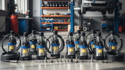
An air operated grease pump uses compressed air to deliver lubricant under controlled pressure. It is common in vehicle workshops, manufacturing plants, and heavy equipment maintenance areas. Unlike a hand-operated grease gun, it can supply grease repeatedly with less physical effort. Its value becomes clear beside a large excavator or a production-line bearing.
The pump normally includes an air motor, grease container, follower plate, and delivery hose. Compressed air moves a piston inside the motor. That movement drives a second piston through the grease. The pump then pushes lubricant toward a fitting, injector, or centralized lubrication system. Changing the air pressure can influence output pressure and flow. However, the exact performance depends on grease thickness, hose length, temperature, and equipment design.
Small details affect real results. A blocked fitting may look like a weak pump. In reality, it can create dangerous back pressure. Experienced technicians check air connections, inspect leaks, and confirm the grease grade before operation. They also follow the manufacturer’s pressure limits and cleaning instructions. Never assume every pump handles the same lubricant. Some models struggle with cold, heavily thickened grease. That lesson is easy to miss.
This guide explains how an air operated grease pump works, how its main parts interact, and where performance problems begin. It also considers practical selection, routine maintenance, and safe operation. The explanation focuses on verified mechanical principles and workshop experience. Still, equipment varies, and no general guide replaces the supplier’s manual or a trained inspection. Understanding the process makes troubleshooting clearer, even when the first diagnosis is wrong.
An air operated grease pump is a pneumatic device that transfers grease from a pail, drum, or bulk container into machinery. It uses compressed air to drive a reciprocating air motor. That motion moves a grease piston, creating pressure and delivering lubricant through a hose, meter, or injector. The main purpose is controlled lubrication in workshops, factories, mines, and mobile maintenance areas.
It reduces the physical effort needed to operate a manual grease gun. It also helps reach fittings placed behind guards, frames, or hot equipment. A follower plate can press grease toward the suction tube, reducing air pockets. Still, the system is not completely automatic. Grease temperature, consistency, hose length, and air pressure strongly affect output. A datasheet rating is only a starting point.
The U.S. Department of Energy’s Improving Compressed Air System Performance sourcebook reports that compressed-air leaks can waste 20–30% of compressor output. That figure matters because a leaking pneumatic line can reduce pump performance and increase operating costs. In field use, technicians should inspect couplings, clean the suction path, and confirm the grease grade before pumping. Small mistakes matter. Over-lubrication can damage seals or bearings, while insufficient lubrication accelerates wear. The equipment is simple, but its results depend on disciplined setup and regular observation.
An air-operated grease pump uses compressed air to drive a reciprocating piston or plunger. The pump multiplies the air pressure according to its pressure ratio, producing the higher pressure needed to deliver grease through long lines, fittings, and bearings.
Example: A pump with a 50:1 pressure ratio can theoretically produce about 2,000 to 5,000 psi of grease outlet pressure when supplied with 40 to 100 psi of compressed air. Actual performance depends on grease consistency, hose length, temperature, flow resistance, and pump condition.
An air operated grease pump uses compressed air to move lubricant through a delivery line. Its air motor receives pressure from the plant’s air system. A spool valve then redirects airflow, creating repeated piston strokes. Each stroke draws grease into the cylinder and pushes it toward the outlet. The pump works without an electric drive. This matters in wet, dusty, or mobile service areas.
The key components each control a different risk. The reservoir stores grease, while a follower plate presses thick lubricant toward the suction tube. The piston creates flow, and inlet and outlet check valves prevent backflow. A pressure regulator controls operating force. A relief valve protects the hose and fittings if pressure rises unexpectedly. The coupler connects to the grease fitting, but poor alignment can still cause leakage. According to the U.S. Department of Energy, compressed air may account for about 10% of industrial electricity use, so inefficient air supply deserves attention. That figure is broad, not a pump-specific measurement. Real consumption varies.
Tips:
Use grease matching the pump’s permitted NLGI grade. Check the air filter before flow weakens. Inspect seals for swelling, cracking, or dry edges. Keep the suction tube fully submerged. A small air leak can become expensive over time. DOE guidance recommends routine leak surveys and pressure management. Do not assume higher pressure means faster lubrication; it may damage seals or overload fittings. Allow room for mistakes during maintenance, because grease contamination is easy to miss.
An air operated grease pump uses compressed air to move lubricant through a delivery line. Instead of relying on an electric motor, it converts air pressure into mechanical movement. This design suits workshops, maintenance areas, and mobile lubrication systems.
Compressed air enters an air valve and pushes a diaphragm or piston. The movement creates suction inside the pump chamber. An inlet check valve opens, allowing grease to enter from the container. During the return stroke, the inlet closes while an outlet valve opens. Grease then moves toward the hose, fitting, or dispensing gun. The air cycles repeatedly, producing steady pressure and flow. The air and grease remain separated, which helps protect the lubricant from contamination.
The process sounds simple. Field conditions are not always simple. Thick grease, cold temperatures, restricted hoses, or excessive air pressure can reduce performance. A regulator helps control output and limits unnecessary wear. Pressure should match the grease type and application, not merely the pump’s maximum rating. Small leaks also matter; they can cause irregular cycling and wasted air.
An air-operated grease pump converts compressed air into controlled lubricant movement. The motor drives a piston, while a follower plate keeps grease near the suction inlet. Delivery has three practical stages: suction, pressure building, and discharge. Small details matter. At suction, the piston rises and creates a low-pressure zone inside the pump tube. Grease moves from the drum through the follower plate and inlet check valve. When grease is cold, this stage often becomes the real bottleneck.
On the return stroke, the air motor shifts direction automatically. The lower piston forces grease through an outlet check valve. Pressure rises until downstream resistance is overcome. With a 50:1 pressure ratio, 0.6 MPa air can theoretically produce about 30 MPa grease pressure. Actual output is lower. Backpressure, hose length, fitting size, and trapped air consume capacity. Field checks should watch for pulsing, dry strokes, or a collapsing follower plate.
At discharge, grease travels through the hose, swivel, metering valve, and fitting. A clean, firm connection matters. The U.S. Department of Energy’s compressed-air performance sourcebook states that leaks can waste 20–30% of compressor output. It also identifies compressed air as roughly 10% of industrial electricity use. The Carbon Trust reports similar leakage losses in poorly maintained systems. These figures affect every grease cycle. ISO 6743-9 classification still needs checking. Grease compatibility is easy to overlook, and mixing products can change texture or pumpability. I would not treat smooth discharge as proof of correct lubrication. Volume, pressure, fitting condition, and bearing requirements must be verified.
| Stage | Grease Delivery Step | What Happens Inside the Pump | Main Components Involved | Typical Operating Data | Practical Function |
|---|---|---|---|---|---|
| 1 | Compressed-Air Supply | Compressed air enters the pneumatic motor or air-control section. The air energy is converted into reciprocating mechanical motion rather than being mixed with the grease. | Air inlet, filter-regulator, control valve, air motor, exhaust muffler | Common air pressure: approximately 3–8 bar (45–120 psi), depending on pump design and required output | Provides the driving force and allows the delivery rate to be adjusted by regulating air pressure or flow. |
| 2 | Air-Motor Stroke Initiation | An internal shuttle, spool, or pilot-operated valve redirects compressed air to one side of the pneumatic piston. The piston begins a power stroke. | Pneumatic piston, spool or shuttle valve, pilot passages, seals | Motion type: reciprocating; the air motor reverses automatically at the end of each stroke in many designs | Creates repeated pump cycles without an electric motor at the grease-pumping section. |
| 3 | Mechanical Power Transfer | The pneumatic piston moves a connecting rod or directly drives a grease piston/plunger. The air motor and material pump are commonly arranged in a single reciprocating assembly. | Connecting rod, material piston or plunger, packing, cylinder | Typical pump ratio: about 10:1 to 70:1 for many industrial grease pumps; the exact ratio is model-specific | Multiplies available air pressure to generate higher grease outlet pressure at a lower material flow rate. |
| 4 | Grease Pick-Up and Suction | As the grease piston moves through its suction stroke, pressure in the lower pump chamber falls. Atmospheric pressure acting on the grease surface, often assisted by a follower plate, pushes grease into the inlet passage. | Grease container, follower plate or ram, suction tube, inlet check valve | Suitable materials: commonly NLGI grades 0–2; higher grades may require short suction paths or a follower-assisted system | Reduces air pockets and helps maintain a continuous grease supply to the pumping chamber. |
| 5 | Inlet Check-Valve Opening | The inlet check valve opens when the pressure in the pump chamber is lower than the pressure in the suction passage. Grease flows into the chamber while reverse flow is restricted. | Ball, poppet, spool, or spring-loaded inlet check valve; valve seat | Flow condition: one-way flow; valve performance depends on grease consistency, contamination, and seat condition | Controls the direction of grease movement and supports reliable priming. |
| 6 | Suction Valve Closure | When the grease piston changes direction, the inlet valve closes. This isolates the filled pump chamber from the supply side before compression begins. | Inlet valve, valve seat, spring or gravity-assisted closing mechanism | Key requirement: the valve must seal against the working grease pressure to prevent backflow and loss of prime | Prepares the chamber for positive displacement during the delivery stroke. |
| 7 | Grease Compression | The material piston moves into the filled chamber, reducing its volume and raising grease pressure. Grease is displaced toward the outlet side. | Grease piston, pump cylinder, piston seal or packing | Displacement principle: positive displacement; output is affected by piston size, stroke length, cycle rate, and grease resistance | Generates the pressure needed to overcome hose, fitting, manifold, and application resistance. |
| 8 | Outlet Check-Valve Opening | When chamber pressure exceeds downstream pressure, the outlet check valve opens and allows the compressed grease to leave the pump chamber. | Outlet ball or poppet valve, outlet seat, discharge passage | Opening condition: pump-side pressure must exceed downstream pressure plus the valve’s cracking resistance | Prevents grease from returning from the discharge line into the pump chamber. |
| 9 | Discharge Through the Outlet | Grease travels through the outlet fitting, hose, divider block, meter, or applicator to the lubrication point. The air motor continues cycling when additional delivery is required. | Outlet fitting, high-pressure hose, meter, divider, grease gun, applicator | Representative output: often several hundred grams per minute, but actual flow varies widely with air supply, grease grade, temperature, and back pressure | Delivers measured or continuous grease to bearings, bushings, joints, and other lubrication points. |
| 10 | Automatic Reversal and Refill | At the end of the stroke, the air-control mechanism redirects compressed air to reverse the pneumatic piston. The material piston returns, the outlet valve closes, and the inlet valve opens for the next suction cycle. | Air-control valve, pilot valve, piston rod, inlet and outlet check valves | Cycle behavior: reciprocating pumps may stall or stop against pressure until the outlet pressure is reduced or the control setting changes | Repeats the suction, compression, and discharge sequence automatically. |
| 11 | Pressure Regulation and Stopping | If downstream resistance rises, the pump slows and may stop when forces balance. Closing the dispensing valve can allow the pump to hold pressure, provided the system is designed for that condition. | Air regulator, shut-off valve, pressure-relief device, gauge, dispensing valve | Safety principle: every installation should include pressure-rated hoses and suitable overpressure protection where required | Helps control lubricant quantity, protect components, and reduce unnecessary air and grease consumption. |
| 12 | Exhaust and Heat Management | Used compressed air exits through the pneumatic exhaust. The grease remains in the material circuit, while the air circuit is vented separately. | Exhaust port, muffler, air valve, seals | Operating consideration: exhaust noise, air cleanliness, moisture, and ventilation can affect service life and workplace comfort | Completes the pneumatic cycle and supports repeated operation without electrical ignition sources at the drive. |
Data ranges are representative engineering values rather than universal specifications. Actual pressure, flow, pump ratio, grease compatibility, and temperature limits depend on pump construction, hose length, lubricant consistency, air quality, and system back pressure.
An air operated grease pump uses compressed air to move a piston and push grease through a hose. It serves machinery that needs frequent, controlled lubrication. Common applications include truck chassis, excavators, agricultural equipment, conveyor bearings, and factory hinges. Technicians can reach distant fittings without carrying a heavy manual lever gun.
Steady pressure is another advantage. The operator can apply grease more evenly, reducing missed fittings and tired hands. A sealed delivery path also helps limit dust entering the lubricant. However, more pressure does not always mean better lubrication. Excess grease can damage seals, increase heat, or force contaminants deeper into a bearing. This is an easy mistake during busy maintenance shifts.
Good maintenance starts with clean air. Drain moisture from the compressor system, inspect the regulator, and replace clogged filters. Check the hose, couplers, and fittings for cracks or leakage before each shift. Keep the grease container covered, and confirm compatibility before changing grease types. Mixing incompatible products may cause separation or poor flow.
Watch the pump while it operates. Irregular cycling can indicate trapped air, a blocked outlet, or low grease. Prime the system after replacing an empty container. Release air pressure before cleaning or repairing any part. Do not ignore small leaks; they often become larger failures. Maintenance records should include grease type, service date, pressure settings, and unusual noise. Good records reveal patterns that memory misses.