A ball check valve is a compact device that controls fluid movement inside a pipeline. It allows flow in one direction and helps prevent reverse movement when pressure changes. Unlike a manually operated valve, it usually works automatically through pressure differences.
Inside the body, a movable ball sits against a shaped seat. When inlet pressure rises, the ball lifts away from the seat, creating a flow path. When flow slows or reverses, the ball returns to its seat and blocks the passage. Simple mechanics. Reliable results.
In practical systems, the valve may handle water, oil, air, or certain chemical fluids. Material selection still matters. Stainless steel, plastic, and elastomer components behave differently under heat, pressure, and chemical exposure. A valve that performs well on a clean water line may struggle with abrasive solids or thick fluids.
Installation also affects performance. The flow arrow must match the intended direction. Poor alignment, trapped debris, or an unsuitable size can cause leakage and pressure loss. That detail is easy to overlook. Even a well-made ball check valve cannot correct a badly designed pipeline.
This guide explains the valve’s internal movement, common applications, benefits, and limitations. It also considers maintenance observations that technicians often learn through repeated inspection. No valve is perfect. Understanding its operating conditions is more useful than trusting a specification sheet alone.
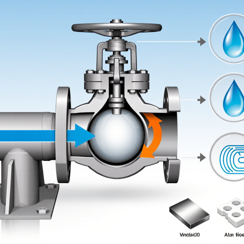
A ball check valve is a mechanical device that permits fluid to move in one direction. Its primary purpose is to prevent reverse flow in a piping system. Inside the valve body, a rounded ball rests against a sealing seat. When inlet pressure rises, the fluid pushes the ball away from the seat. The passage opens, allowing water, air, or another compatible fluid to continue downstream.
When pressure drops or flow attempts to reverse, the ball moves back onto the seat. This action blocks the passage and protects pumps, tanks, and connected equipment from backflow. Some models rely on gravity, while others use a spring to return the ball quickly. The design is compact and has few moving parts. That sounds simple.
In practical piping work, correct installation still matters. The valve must match the flow direction marked on its body. A horizontal installation may work differently from a vertical one, depending on the ball design and pressure conditions. During inspection, technicians often check for sediment, worn seats, or a ball that moves unevenly. Even a small particle can prevent complete closure. This is easy to overlook.
Ball check valves are commonly used in drainage lines, pump discharge piping, and low-maintenance fluid systems. Their purpose is not to regulate flow precisely. They provide one-way protection. Selecting the wrong size can increase pressure loss or cause noisy operation, so flow rate, fluid type, temperature, and installation position deserve careful review.
What Is a Ball Check Valve and How Does It Work?
Key Components and Internal Structure
A ball check valve uses a free-moving spherical ball to control one-way flow. Its body contains the inlet, outlet, ball, seat, and guiding chamber. Some designs also include a spring. The ball is usually made from metal, coated metal, or an engineered polymer. Material choice depends on pressure, temperature, and fluid compatibility.
When upstream pressure rises, the ball lifts from its seat. Fluid then passes through the open flow path. When pressure falls or reverses, the ball returns to the seat. Gravity, backpressure, or a spring may assist closure. The seat must align closely with the ball. Even small damage can create leakage, vibration, or noisy operation.
Simple movement. Critical geometry.
Industry testing standards, including API 598 and ISO 5208, evaluate valve leakage and pressure performance. These standards matter because a visually sound valve can still fail under pressure. The Business Research Company’s 2024 Valves Global Market Report identifies continued demand for industrial valves, with infrastructure and process industries supporting market growth. That growth does not make every design suitable. Flow rate, viscosity, installation angle, and solids content still require careful review.
A common mistake is assuming a larger valve always reduces pressure loss. Internal clearance can increase, but poor ball guidance may cause impact and wear. In field inspections, checking the seat surface, ball movement, and debris buildup often reveals more than external appearance.
| Component or Feature | Internal Structure | Function | Operating Principle or Typical Specification |
|---|---|---|---|
| Valve Body | Main pressure-containing shell with inlet and outlet flow passages. | Contains the internal parts and directs fluid through the valve. | Common body materials include metals, thermoplastics, and corrosion-resistant alloys, selected according to pressure, temperature, and fluid compatibility. |
| Ball | A spherical movable element positioned between the inlet and outlet seats. | Acts as the closing member that stops reverse flow. | Forward flow lifts or rolls the ball away from the seat; reverse flow pushes the ball onto the seat. |
| Valve Seat | A precisely shaped sealing surface surrounding the flow opening. | Provides the contact area needed to reduce leakage when the valve closes. | Seat geometry and material influence sealing performance, pressure loss, wear resistance, and chemical compatibility. |
| Inlet and Outlet Ports | Two openings connected to the upstream and downstream piping. | Allow fluid to enter and leave the valve in the permitted direction. | Port size and connection type affect flow capacity, installation method, and pressure drop. |
| Ball Guide or Cage | An internal guide, where fitted, that limits excessive ball movement. | Helps keep the ball aligned with the seat and reduces unstable movement. | Some compact designs rely on the body cavity instead of a separate cage. |
| Retainer or Cover | A removable or integrated section that holds internal components inside the body. | Provides access for inspection or service in designs that are not permanently sealed. | Construction varies by valve design; some bodies are one-piece and have no serviceable cover. |
| Flow Direction Arrow | A marking located on the outside of the valve body. | Shows the permitted direction of normal fluid flow. | Correct orientation is essential because a ball check valve is designed for one-way flow. |
| Forward Flow | Pressure at the inlet becomes greater than pressure at the outlet. | Moves the ball away from the seat and opens the passage. | The opening force must overcome the ball's weight, friction, and any resistance caused by the guide or seat. |
| Reverse Flow | Outlet pressure becomes equal to or greater than inlet pressure. | Pushes the ball back against the seat to block the passage. | The valve closes automatically without an external actuator or electrical control signal. |
| Cracking Pressure | The minimum differential pressure required to move the ball off the seat. | Determines when the valve begins to open. | It depends on ball weight, orientation, seat friction, internal geometry, and any spring fitted in the design. |
| Pressure Drop | Pressure difference between the inlet and outlet while the valve is open. | Represents the energy loss caused by the valve and its internal flow path. | A larger pressure drop can occur at high flow rates, with restrictive passages, or when the ball partially obstructs the opening. |
| Sealing Performance | Contact between the ball and the seat around the flow opening. | Limits backflow when the valve is closed. | Actual shutoff performance depends on seat condition, ball surface, fluid properties, pressure, temperature, and installation. |
| Spring-Loaded Option | A spring is installed behind the ball or within the guiding assembly. | Assists closing when flow decreases or reverses. | Spring-loaded designs can close in more mounting positions, but the spring adds resistance and may increase cracking pressure. |
| Mounting Orientation | The valve may be installed horizontally or vertically, depending on its design. | Ensures the ball moves correctly and returns reliably to the seat. | Non-spring designs can be sensitive to gravity; the manufacturer's operating orientation and flow arrow should be followed. |
| Typical Applications | Installed in piping systems carrying liquids, gases, or compatible slurries. | Prevents reverse flow and helps protect pumps, compressors, filters, and process equipment. | Common applications include water systems, drainage, chemical service, process piping, and pump discharge lines, subject to material and pressure compatibility. |
A ball check valve uses a round ball to control fluid movement through a pipe. When inlet pressure rises, the ball moves away from its seat. This opens a passage and lets liquid or gas flow forward. When pressure falls, reverse flow pushes the ball back onto the seat. The sealed contact blocks unwanted backflow.
The ball may be guided by the valve body or held with a spring. A spring-loaded design can close faster, especially when flow changes suddenly. A free-floating ball needs enough reverse pressure to seal properly. This difference affects installation, pressure loss, and response time. In practical piping inspections, technicians check the flow arrow carefully. Incorrect installation can make the valve restrict normal flow.
Fluid cleanliness also matters. Dirt, scale, or small metal particles can keep the ball from seating fully. A tiny gap may cause leakage, noise, or repeated cycling. Thick fluids can slow ball movement, while high flow speeds may create water hammer. The valve is compact and reliable, but not foolproof. Engineers should match its size, seat material, pressure rating, and orientation to the system. Real operating conditions sometimes expose weaknesses that a catalog specification does not show.
A ball check valve uses a movable ball to control one-way flow. When upstream pressure rises, the ball lifts from its seat. Reverse pressure pushes it back, sealing the passage. The design is simple, but ball material, seat geometry, and line velocity strongly affect performance. In field inspections, a coated steel ball often handles abrasive service better than a softer plastic ball. Selection still depends on temperature and chemical compatibility.
Common types operate differently. A standard gravity ball check valve needs enough flow pressure to lift the ball. It may create noticeable pressure loss in low-flow systems. A spring-loaded ball check valve closes faster because the spring forces the ball toward its seat. This helps reduce reverse-flow shock, although the spring adds opening resistance. Lift check valves use a guided disc or piston and suit higher-pressure piping. Swing check valves use a hinged disc, while dual-plate wafer valves use two spring-assisted plates and require less installation space.
A 2023 Grand View Research report estimated the global industrial valves market at about USD 78.7 billion. That figure reflects broad valve demand, not ball check valves alone. The distinction matters. In wastewater lines, a swing design may tolerate larger solids, while a ball valve can clog if debris blocks the seat. No check valve is perfectly silent or maintenance-free.
I would verify flow direction, cracking pressure, and expected backflow before specifying one. Field conditions are often less tidy than catalog diagrams suggest.
A ball check valve uses a spherical ball to control one-way flow. Fluid pressure lifts the ball from its seat. When flow stops or reverses, the ball returns and blocks the passage. Gravity, backpressure, or a spring may assist closing. Its action is automatic.
These valves suit water systems, drainage lines, pump outlets, chemical dosing equipment, and some low-pressure air services. They can handle minor particles better than delicate flap designs. However, that benefit has limits. Thick sludge, sharp solids, or sticky deposits may prevent proper seating. Flow direction, pressure, temperature, and material compatibility must match the application. Incorrect selection can cause leakage, noise, or poor pump performance. Smaller bores may also create noticeable pressure loss. It is tempting to call them maintenance-free. That claim is too neat.
Maintenance is simple, but still necessary. Isolate and depressurize the line before inspection. Check the ball for scoring, swelling, cracks, or trapped grit. Examine the seat and seals under good lighting. Keep it accessible. Flush suitable systems, but do not assume flushing removes hardened deposits. Replace damaged parts according to the valve design and service conditions. Field technicians should also check installation direction, nearby pipe strain, and repeated water hammer. A valve can appear clean while its seat is already worn. Do not guess. Record leakage, operating pressure, and inspection dates to support safer decisions during future servicing.