Choosing high pressure fittings in 2026 requires more than comparing thread sizes and catalog prices. A fitting may look suitable on a clean drawing, yet fail when vibration, heat, corrosion, and pressure cycles combine. The decision should connect operating data with recognized standards, verified materials, and documented testing. Small details matter. A scratched sealing face can become a leak path.
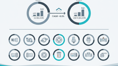
Industry conditions make this discipline more important. The International Energy Agency’s World Energy Investment 2024 reported global energy investment above 3 trillion dollars, with clean energy receiving about 2 trillion dollars. New hydrogen, carbon-management, power, and gas projects are creating demanding connection requirements. The U.S. Energy Information Administration also continues to report substantial natural gas production and infrastructure activity, where pressure integrity remains central. These figures do not determine a fitting’s specification, but they show the scale of systems depending on reliable connections.
Engineers should check pressure and temperature ratings, material compatibility, corrosion resistance, connection type, and installation access. ASME B16.5 provides dimensional and pressure-temperature guidance for flanges, while API 6A supports equipment requirements in upstream well-control applications. ISO 15156 may guide material selection where hydrogen sulfide creates cracking risks. Certification alone is not enough. Traceability, heat numbers, inspection records, and manufacturer experience deserve equal attention. A cheaper fitting can become expensive after one shutdown.
There is no universal best choice. A stainless fitting may resist corrosion but still suffer galling during assembly. A forged carbon-steel option may offer strength, yet require stronger coating controls. This guide explains how to balance safety, lifecycle cost, standards, and real operating conditions when selecting high pressure fittings for 2026 projects.
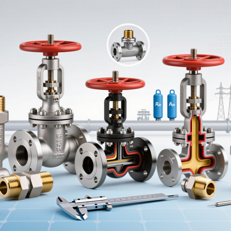
Choosing high pressure fittings starts with design inputs, not catalog appearance.
Record maximum operating pressure, normal pressure, and transient spikes. A pump start can create a sharp pressure wave. Rate the fitting for the highest credible pressure at the actual temperature.
Temperature changes material strength and seal behavior. Keep a written safety margin.
Do not confuse working pressure with burst pressure. That mistake is expensive.
Flow data should include minimum, normal, and peak rates.
Calculate velocity through the tube and fitting bore. A narrow passage can create pressure loss, heat, and vibration.
Check gas compressibility when the medium is gas. For liquid service, consider cavitation near restrictions.
Media details matter too. List concentration, moisture, particles, and cleaning chemicals.
Verify body, seal, and tube materials against compatibility tables. Tables help. They do not replace testing.
Tube size must be precise: outside diameter, wall thickness, and tolerance.
Metric and inch dimensions may look similar but seal differently. Select the connection style after these inputs are fixed.
Inspect insertion depth, surface condition, and alignment during assembly.
In real installations, poor tube cutting causes more trouble than expected. A clean cut is not always square.
Pressure-test the completed assembly with controlled procedures and calibrated instruments. Record temperature, test medium, and results.
Have a qualified engineer review unusual loads, pulsation, or corrosive media. Recheck assumptions when the process changes.
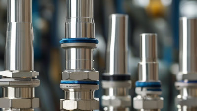
Choosing a high-pressure flange starts with the pressure class, not the bolt count. ASME B16.5 covers flanges and flanged fittings from NPS 1/2 through NPS 24. It defines Class 150, 300, 400, 600, 900, 1500, and 2500. These are rating classes, not direct pressure values. Source: ASME B16.5, Pipe Flanges and Flanged Fittings.
At 100°F, ASME pressure-temperature tables list approximately 285 psig for Group 1.1 carbon-steel Class 150 flanges. A comparable Class 300 rating reaches about 740 psig. Material group changes the result. Temperature changes it again. Never choose Class 2500 because it “sounds safer.” Its suitability depends on material, temperature, gasket, bolts, and design conditions. The standard does not replace system calculations.
In practice, record design pressure, temperature, fluid, corrosion allowance, NPS, and facing before ordering. Then verify the material group, dimensions, bolt holes, face finish, and pipe schedule. A Class 600 flange can still leak if the gasket or bolts are unsuitable. That mistake is common in rushed projects. ASME B16.5 supplies rating and dimensional data, while project codes may impose stricter requirements. The IEA’s World Energy Investment 2024 report estimated global energy investment above 3 trillion dollars, including about 2 trillion dollars for clean energy. More projects mean more selections to check. I would recheck the adopted standard edition. Memory is not a specification.
At 6,000–20,000 psi, fitting selection cannot rely on tube diameter alone. Confirm the tube’s outside diameter, material, temper, operating temperature, and actual wall thickness. Then compare these details with the fitting’s pressure rating for identical service conditions. Use the lowest-rated component as the system limit. Do not guess.
Wall thickness affects pressure capacity, internal flow, bending resistance, and fitting compatibility. A thicker tube may withstand higher pressure, but it can require a different cone, thread, or installation procedure. Check the manufacturer’s pressure tables carefully, including ratings for cyclic service and elevated temperatures. A fitting rated for static pressure may not suit repeated pressure pulses.
In field inspections, small scratches near the tube end often become serious leak paths. Cut the tube squarely, remove burrs, and keep sealing surfaces clean. Tighten the connection according to a verified procedure, not personal experience. I have seen careful assemblies fail because the tube wall was measured incorrectly. That mistake deserves attention. Record the material certificate, wall measurement, torque method, and pressure-test result for each critical line. Recheck assumptions when the design changes.
High-pressure fittings should be selected from operating data, not pressure ratings alone. NACE’s IMPACT study estimated global corrosion costs at about $2.5 trillion, or 3.4% of worldwide GDP. That figure shows why alloy choices deserve engineering attention. Record chloride concentration, pH, oxygen, H2S partial pressure, flow velocity, and shutdown conditions. Small differences matter. A wet, stagnant pocket can attack faster than a clean production line.
Temperature changes corrosion behavior and material strength. Higher temperatures may accelerate general corrosion, while low temperatures can increase fracture risk in some alloys. Compare test data at the actual service temperature. Do not rely on a room-temperature certificate. Nickel alloys may tolerate aggressive chlorides better than many stainless steels, but cost and galling still require review. Duplex grades can offer strength and chloride resistance, yet welding quality remains critical.
For sour service, apply ISO 15156 requirements to the complete material condition, including hardness, heat treatment, and environmental limits. Check H2S exposure against the standard’s documented tables and qualification methods. A fitting may pass a pressure test and still fail sulfide stress cracking controls. That mistake is expensive. Keep mill certificates, traceability records, and inspection results together. I have seen alloy charts simplify reality too much; field chemistry often changes. Recheck assumptions after commissioning, especially when water cut or acid-gas content rises.
How to Choose High Pressure Fittings in 2026?
Pressure selection should begin with the complete design envelope, not the catalog rating. Confirm design pressure, temperature, fluid, corrosion allowance, and cyclic loading. ASME B31.3 requires hydrostatic testing at a minimum of 1.5 times design pressure, with adjustments when test and design temperatures differ. Check the governing edition and project specification. A careless assumption here can invalidate an otherwise suitable fitting.
Make the test physical. Use calibrated gauges, documented hold times, controlled pressurization, and a safe exclusion zone. Inspect threads, weld ends, seals, and visible distortion before and after testing. Material certificates, heat numbers, pressure ratings, and traceability should follow every fitting. ASME B16.5 and ASME B16.11 provide dimensional and rating requirements for common flanges and forged fittings, but they do not replace the piping code’s test obligations.
The U.S. Bureau of Labor Statistics recorded 5,283 fatal workplace injuries in 2023, with transportation and material-moving incidents remaining significant contributors. A pressure test cannot remove every hazard, but disciplined isolation reduces exposure. The International Association of Oil & Gas Producers’ safety reports also show why performance data and contractor controls matter across energy operations. Do not treat 1.5× as a universal shortcut. Actual test pressure may require engineering adjustment, and some projects demand additional examination. Mistakes happen. Review the calculation.
| Evaluation Dimension | Engineering Input or Requirement | Reference Value / Calculation | Selection or Verification Action | Safety Result |
|---|---|---|---|---|
| 1. Pressure and Hydrostatic-Test Verification | ||||
| Design pressure: low-pressure example | 100 bar(g) | Hydrotest minimum = 1.5 × 100 bar = 150 bar(g) | Select a fitting whose pressure rating at the design temperature is at least 100 bar(g), then confirm that the complete test assembly can safely withstand 150 bar(g). | Pass only after component and assembly ratings are confirmed. |
| Design pressure: medium-pressure example | 160 bar(g) | Hydrotest minimum = 1.5 × 160 bar = 240 bar(g) | Check fitting body, threads or weld ends, valves, gaskets, tubing, instruments, and temporary test blinds against the test pressure. | Use the lowest-rated component as the system limit. |
| Design pressure: high-pressure example | 250 bar(g) | Hydrotest minimum = 1.5 × 250 bar = 375 bar(g) | Use a documented pressure-rating basis and verify wall thickness, end connection design, seal compatibility, and test boundaries before pressurization. | High-pressure testing requires a formal test procedure and exclusion zone. |
| Unit conversion | Pressure values shown in bar(g) | 1 bar = 0.1 MPa; therefore 375 bar = 37.5 MPa | Keep all design, test, gauge, and certification documents in consistent units. | Reduces calculation and instrument-reading errors. |
| Code pressure adjustment | Hydrotest pressure is normally based on the applicable piping-code requirement. | Nominal basis used here: 1.5 × design pressure | For ASME B31.3 projects, verify the applicable edition, material allowable stresses, test temperature, component limitations, and any required stress-ratio adjustment with the responsible engineer. | Do not treat 1.5× as a substitute for the complete code calculation. |
| 2. Temperature and Material Compatibility | ||||
| Design temperature: ambient process service | 38°C | Use the fitting rating applicable at or above 38°C. | Confirm material, pressure class or manufacturer rating basis, corrosion allowance, and connection standard. | Suitable only when the rating covers both pressure and temperature. |
| Design temperature: elevated service | 150°C | Do not use a room-temperature pressure rating without temperature derating review. | Apply the pressure-temperature rating for the exact material grade and fitting type; check gasket and seal temperature limits. | Temperature derating can reduce allowable pressure below the nominal rating. |
| Material selection | Carbon steel, stainless steel, or alloy steel selected by service conditions | Evaluate design temperature, fluid chemistry, chloride exposure, hydrogen service, erosion, and corrosion allowance. | Require material certificates identifying the grade, heat or lot traceability, and applicable mechanical properties. | Material compatibility must be demonstrated, not assumed from appearance. |
| Galvanic compatibility | Dissimilar metallic components in the same wetted system | Electrical potential difference and electrolyte exposure may accelerate corrosion. | Review material combinations, insulation requirements, coating systems, and fluid conductivity. | Reduces premature leakage and loss of wall thickness. |
| 3. Connection and Mechanical Design | ||||
| Connection type | Butt-weld, socket-weld, threaded, flanged, or compression connection | Each connection has different pressure, fatigue, assembly, and inspection requirements. | Match the fitting end connection to the piping specification, wall thickness, joining procedure, and inspection plan. | Avoids incompatible interfaces and weak transition points. |
| Threaded connection | Only where permitted by the project piping class and applicable code | Thread engagement, sealing method, stress concentration, and vibration resistance affect integrity. | Verify thread form, engagement length, sealant compatibility, torque or tightening procedure, and service limitations. | Use additional caution in cyclic, toxic, flammable, or vibration-prone service. |
| Welded connection | Applicable weld procedure and qualified personnel | Weld quality directly affects pressure-boundary integrity. | Confirm qualified welding procedures, welder qualifications, preheat or post-weld requirements where applicable, and required nondestructive examination. | Provides a traceable joining method when properly qualified and inspected. |
| Wall thickness and corrosion allowance | Pressure design thickness plus specified allowance | Required thickness depends on pressure, diameter, material strength, weld quality, temperature, and code rules. | Review fitting dimensions, minimum wall thickness, erosion potential, and remaining-life calculations for existing systems. | Confirms that pressure capability is maintained over the intended service life. |
| Pressure-thrust and support loads | Directional changes, reducers, closed ends, and branch connections | Internal pressure creates unbalanced forces at elbows, tees, reducers, caps, and blind ends. | Check pipe supports, anchors, guides, restraint loads, and equipment nozzle loads. | A correctly rated fitting can still fail if system loads are not supported. |
| 4. Hydrotest Execution and Acceptance | ||||
| Test medium | Clean water, unless prohibited by process or material requirements | Hydrostatic testing stores substantially less energy than pneumatic testing. | Confirm water quality, chloride limits for susceptible stainless materials, draining method, and drying requirements. | Reduces stored-energy risk and post-test corrosion concerns. |
| Pressure gauges | At least two calibrated gauges located where pressure differences may be detected | Gauge range should allow clear reading near the test pressure without exceeding gauge limits. | Verify calibration status, range suitability, installation location, and isolation-valve integrity. | Improves confidence that the measured pressure is accurate. |
| Pressurization rate | Controlled increase in pressure | Remove trapped air before reaching test pressure. | Fill slowly, vent high points, inspect for abnormal movement or leakage, and use a written test sequence. | Limits shock loading and improves leak detection. |
| Leak and pressure acceptance | No visible leakage or unacceptable pressure loss during the specified hold period | Acceptance criteria must be defined by the approved test procedure and applicable code. | Record test pressure, temperature, start and finish times, gauge identification, examination results, and corrective actions. | Creates auditable evidence of test completion. |
| Post-test restoration | Drain, dry, inspect, and return the system to service | Residual water can cause corrosion, freezing damage, contamination, or process upset. | Remove temporary blinds and test equipment, restore insulation, confirm valve positions, and complete final inspection. | Prevents test-related damage after acceptance. |
| 5. Documentation and Final Selection Decision | ||||
| Required documentation | Material certificates, dimensional records, pressure-rating data, inspection reports, and hydrotest records | Documents should identify the component, material, size, rating basis, and traceability information. | Compare certificates with purchase specifications, piping class, drawings, and the bill of materials. | Supports traceability and future maintenance decisions. |
| Minimum selection rule | Design pressure and temperature, fluid compatibility, mechanical loads, connection type, and code compliance | The fitting must satisfy the most demanding applicable condition, not only nominal pressure. | Approve the fitting only after engineering review of rating, materials, dimensions, testing, and documentation. | Select the fitting with a verified design margin and complete compliance record. |