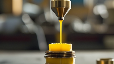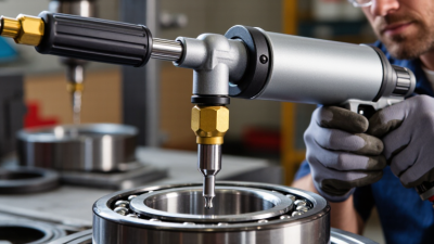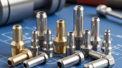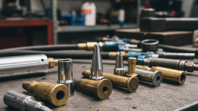
A locking grease gun coupler is a small tool with a demanding job. It connects a grease gun to a Zerk fitting and stays attached during lubrication. Instead of relying only on hand pressure, its locking sleeve grips the fitting mechanically. This helps prevent grease leakage, sudden disconnection, and messy pressure loss.
John Gibbons, founder of LockNLube, describes the practical goal this way: “Greasing should be quick, clean, and easy.” That idea explains why this coupler matters in workshops, farms, garages, and industrial maintenance areas. When the jaws engage, the coupler forms a tighter seal around the fitting. Pressure then travels through the coupler and into the bearing, joint, or bushing.
The process is simple.
Push. Twist. Pump.
To release it, the operator usually pulls back the sleeve before removing the coupler. That step matters. Pulling the grease gun away without unlocking the sleeve may damage the fitting or strain the hose. A worn fitting can still cause trouble, even with a high-quality coupler. The tool cannot correct every maintenance problem.
This guide explains what a locking grease gun coupler is, how its internal mechanism works, and why its design improves everyday lubrication. It also considers compatibility, pressure handling, fitting wear, and safe operation. Some claims about “leak-free” performance deserve careful thought. Real results depend on the coupler, fitting condition, grease viscosity, hose quality, and operator technique. Small details often decide whether lubrication feels clean and controlled or frustratingly messy.
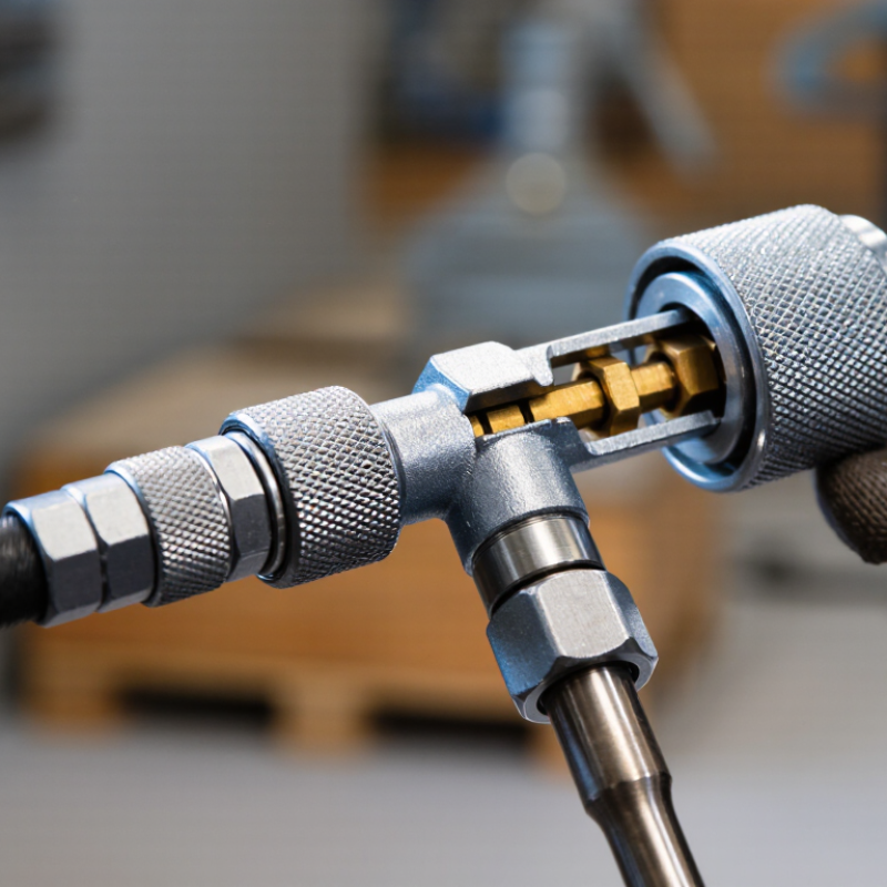
A locking grease gun coupler is a fitting that connects a grease gun to a machine’s grease nipple. Its main purpose is to create a firm, sealed connection during lubrication. Unlike a basic push-on coupler, it uses an internal sleeve or locking mechanism to grip the nipple. This helps prevent the coupler from slipping when pressure rises.
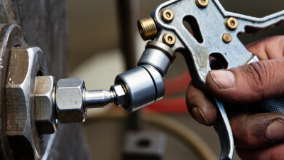
The operator usually presses the coupler onto the nipple and activates its locking sleeve. Once engaged, the jaws hold the fitting in place while grease moves through the center passage. This allows controlled lubrication with both hands available for the grease gun handle.
It can be useful around tight machinery, where repeated disconnection wastes time and creates messy grease leaks.
A good coupler should match the nipple size and tolerate the grease gun’s working pressure. Clean contact surfaces matter. Dirt can block the seal or damage the small internal jaws. In practice, the connection is not perfect every time. Worn nipples, hardened grease, or a damaged coupler can still cause leakage. I recommend checking the seal before pumping forcefully, because excessive pressure may hide a fitting problem rather than solve it. When released correctly, the locking sleeve lets the coupler detach without pulling aggressively on the nipple.
What Is a Locking Grease Gun Coupler and How Does It Work?
A locking grease gun coupler grips a grease fitting without constant hand pressure. Its main body connects to the delivery hose or rigid tube. Inside, hardened jaws engage the fitting’s shoulder. A sliding sleeve locks those jaws in place during pumping. A spring returns the sleeve after release. The internal seal surrounds the fitting and helps prevent grease leakage. Some models also include a swivel, which reduces hose twisting near crowded bearings.
Pressure control depends on the coupler, hose, gun, and fitting condition. According to SKF reliability data, inadequate lubrication contributes to about 36% of premature bearing failures, while contamination contributes about 14%. A clean, properly locked connection therefore supports more than convenience. It helps deliver grease into the intended passage. In practical maintenance, a clogged fitting may mimic a faulty coupler. That mistake wastes time. The operator should inspect the fitting before forcing more pressure. A locking sleeve can also wear, although this detail is often overlooked.
Tips: Wipe the fitting before connection. Push the coupler straight onto the fitting, then slide the locking sleeve forward. Pump slowly and watch for seal damage or abnormal resistance. Never twist the gun aggressively while locked. The U.S. Department of Energy’s Operations & Maintenance Best Practices guide identifies lubrication as a core preventive-maintenance activity. Still, perfect technique is not guaranteed. A coupler may feel secure but leak under pressure, so routine inspection remains necessary.
A locking grease gun coupler connects to a grease fitting through spring-loaded gripping jaws. Before attachment, wipe away dirt and hardened grease around the fitting. Even a small grain can prevent a proper seal. Keep the coupler aligned with the fitting, not tilted.
Push the coupler straight onto the fitting until the jaws surround its head. Then move the locking sleeve or lever into position. This action tightens the internal jaws around the fitting’s narrow shoulder. The connection should feel firm, but it should not require excessive force. A properly attached coupler stays in place while grease pressure builds inside the passage.
Now operate the grease gun with steady strokes. Watch the fitting and coupler for movement, leakage, or damaged seals. If grease escapes around the connection, stop and check the alignment. Many users pull the coupler sideways too soon. That can damage the fitting or leave the jaws stuck under pressure. Release the gun pressure first, then unlock the sleeve and pull the coupler straight back. I still find this step easy to rush, especially in cramped spaces. Taking a few extra seconds usually protects both the tool and the fitting.
A locking grease gun coupler attaches to the spherical head of a grease fitting. Its internal jaws slide over the fitting, grip behind the head, and create a sealed connection while grease is pumped. The fitting’s thread size secures it in the machine, while the coupler locks onto the head itself.
The chart compares nominal thread pitch for common grease-fitting thread standards. Thread pitch identifies how the fitting is installed; the locking coupler grips the fitting head rather than the threaded section.
What Is a Locking Grease Gun Coupler and How Does It Work?
How the Locking Mechanism Controls Grease Flow
A locking grease gun coupler connects the grease gun to a small lubrication fitting. Its internal jaws grip the fitting’s head, while a sliding sleeve holds them in place. This design creates a stable seal around the fitting. Firm contact matters.
The locking mechanism does not directly measure grease flow. Instead, it keeps the connection closed under pressure. Grease starts moving when the gun handle or trigger is activated. Pressure then pushes lubricant through the coupler and into the fitting. When the handle is released, flow stops, but the coupler may remain attached. This distinction is easy to miss.
In practical use, a technician should press the coupler straight onto the fitting before locking it. A slight angle can damage the seal or cause grease to escape around the edges. Never twist the coupler aggressively. Wipe away old grease first, because hardened residue can prevent full engagement. If the coupler will not release, reduce pressure before pulling the sleeve. Forcing it can bend the fitting.
The mechanism is simple, but not foolproof. A worn jaw, damaged seal, or blocked fitting can imitate a flow problem. I would not blame the coupler too quickly. Checking alignment, pressure, and fitting condition gives a more reliable diagnosis.
A locking grease gun coupler connects a grease gun to a machine’s lubrication fitting and stays attached during pumping. Its internal jaws grip the fitting’s head, while a sleeve or locking mechanism holds them in place. This design reduces hand pressure and helps prevent grease from escaping around the connection.
Common types include lever-lock, push-button, and threaded couplers. Lever-lock models suit routine maintenance because they attach quickly and release with a small lever. Push-button versions can work well in tight spaces, where a lever is difficult to reach. Threaded couplers provide a firm connection for stubborn fittings, but they take longer to install. These tools are useful on tractors, construction equipment, industrial bearings, vehicle joints, and workshop machinery. Their main benefits include cleaner lubrication, fewer leaks, and improved operator control. In practice, no coupler is perfect. Worn fittings, excessive pressure, or poor alignment can still cause problems.
Tips: Clean the fitting before connection. Push the coupler straight onto the fitting. Pump slowly and watch for resistance. Do not twist aggressively during removal. If the coupler remains stuck, release pressure from the grease gun first. Inspect the jaws regularly, because small wear can create noticeable leaks. A pressure gauge can also help, although many maintenance workers overlook it. Record the service date and grease type, especially when several machines share one workshop.
| Type or Feature | How It Works | Typical Operating Characteristics | Main Benefits | Common Applications | Important Considerations |
|---|---|---|---|---|---|
| Standard locking jaw coupler | Four hardened jaws grip the outside shoulder of a standard grease fitting. A sleeve or locking collar holds the jaws around the fitting while grease is pumped. | Designed for common hydraulic-type grease fittings; pressure capability varies by construction and seal condition. | Hands-free connection, reduced grease leakage, and a more secure attachment than a basic push-on coupler. | Automotive chassis points, agricultural equipment, construction machinery, industrial bearings, and general maintenance. | The coupler must be released before removal; pulling it off under pressure can damage the jaws or grease fitting. |
| High-pressure locking coupler | Uses a reinforced body, stronger gripping components, and pressure-resistant seals to maintain contact as system pressure rises. | Often selected for high-resistance grease passages; the actual maximum pressure is determined by the specific coupler design. | Helps prevent blow-off and leakage when grease requires greater pumping force. | Heavy equipment, loader pins, excavator joints, industrial machinery, and neglected lubrication points. | High pressure does not mean unlimited pressure. The coupler, hose, gun, fitting, and relief path must all be rated for the application. |
| 90-degree angled locking coupler | Places the coupler outlet at approximately a right angle to the hose or grease gun, allowing access around guards and nearby components. | Best suited to side-facing or partially obstructed grease fittings. | Improves access and reduces awkward hose bending at confined lubrication points. | Vehicle suspension joints, machinery pivots, compact equipment, and fittings positioned behind brackets. | The extra angle can reduce clearance in some locations; verify that the body does not contact surrounding parts. |
| Flexible-hose locking coupler | Connects to a flexible whip hose that absorbs movement between the grease gun and the fitting while the locking jaws remain engaged. | Useful where the operator needs to hold the gun away from moving parts or work at different angles. | Reduces hand fatigue, improves reach, and helps keep the operator away from pinch points. | Large machinery, vehicle undercarriages, agricultural implements, and hard-to-reach pivot points. | Avoid sharp bends, abrasion, and routing near hot or moving components. Inspect the hose for cuts and bulges. |
| Swivel locking coupler | A rotating joint allows the coupler or hose connection to change orientation while the fitting remains engaged. | Suitable for changing approach angles and applications where hose twisting is common. | Limits hose torsion, improves maneuverability, and makes alignment easier. | Service bays, mobile equipment, articulated machinery, and multiple grease points with different orientations. | The swivel is not a substitute for correct alignment. Check for leakage or stiffness during routine inspection. |
| Flush-fitting or low-clearance coupler | Uses a compact contact profile for grease fittings recessed into plates, blocks, or limited-clearance joints. | Requires compatible flush or low-profile fittings; it is not intended for every conventional protruding fitting. | Provides access where a conventional jaw coupler cannot fit. | Compact machinery, agricultural implements, industrial assemblies, and protected lubrication points. | Coupler and fitting profiles must match. Forcing an incompatible coupler can damage the seal or fitting. |
| Locking mechanism | A sliding sleeve, lever, or collar moves the internal jaws between an open position and a gripping position. | The coupler should be fully seated before the locking mechanism is engaged. | Maintains connection without continuous hand pressure and helps keep the seal centered. | Any routine lubrication task requiring a secure, repeatable connection. | Keep the mechanism clean. Dirt, dried grease, or damaged jaws can prevent complete engagement. |
| Typical connection sequence | Clean the fitting, align the coupler, press it fully onto the fitting, activate the lock, pump grease, release pressure, and then unlock and remove it. | The exact release method depends on the coupler design and grease gun configuration. | Promotes cleaner lubrication, consistent engagement, and safer removal. | Preventive maintenance programs, fleet servicing, equipment repairs, and workshop lubrication routines. | Never place fingers near the coupler while pressure is being released, and do not use a damaged fitting. |
| Primary benefits | The locking jaws hold the coupler in place while the grease gun delivers lubricant through the fitting. | Performance depends on fitting condition, coupler compatibility, seal quality, and correct operating technique. | Less grease waste, fewer accidental disconnections, improved operator control, and more reliable lubrication. | Automotive, agricultural, construction, material-handling, industrial, and marine maintenance. | A locking coupler cannot correct a blocked grease passage, a damaged fitting, or an unsuitable lubricant. |
Note: Pressure ratings, fitting compatibility, temperature limits, and seal materials vary by coupler design. Always follow the specifications supplied for the selected equipment.